Safeguards either must prevent entry into a hazardous area or detect entry into the hazardous area and eliminate the hazard before it can present a danger. Guards (physical barriers) must be designed to keep individuals from reaching the hazard. On the other hand, devices that protect individuals by detecting entry to a hazardous area must be mounted at a sufficient distance from the hazard(s) so that the machine will stop before the operator’s hand or other body part can reach this hazardous point.
Calculating the minimum safe mounting distance is vital to ensure worker safety, while excessive mounting distances use up valuable floor space and also can increase the time required to service machinery, which in turn reduces throughput. This article will explain how to calculate safe mounting distances for many types of safeguards.
Protecting employees against machinery hazards is required to comply with regulations and to protect employees. The same equipment that prevents injuries also can make a positive impact on the bottom line. The cost of a work-related injury goes far beyond hospital and medical costs. Common additional costs that result from an accident include rehabilitating and retaining the injured worker, time spent by management on the incident, machine downtime and possible litigation.
Safety measures need to minimize the risk of injury while providing access for functions – such as loading work pieces – and maintaining the machinery. The best protection is the method that offers the maximum safety level with minimal impact on machine operations at an affordable cost. A key factor is how often entry is required. For example, with machines operating at high production rates, operators frequently need to enter the hazardous area to load and unload parts. On the other hand, low production rate equipment typically requires less-frequent entry. Applications that require frequent entry generally require faster and more convenient access in order to maintain high throughput.
Height of Hazard
The first variable to consider is the height of the hazard. If the hazard is sufficiently far above the ground or expected working surface then guarding is not required. The relevant OSHA standard, 29 CFR 1910.219 – Mechanical Power-Transmission Apparatus, says that a hazard that is more than 7 feet from the working surface does not need to be guarded.
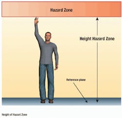
American National Standards Institute (ANSI) B11.19-2010 – Performance Criteria for Safeguarding requires that a low-risk hazard needs to be safeguarded unless it is 2,500 mm (98.4 in.) or more from the working surface and that a high-risk hazard needs to be safeguarded unless it is 2,700 mm (106.3 in.) or more from the reference plane as shown in Figure 1. This portion of ANSI B11.19-2010 has been harmonized with Canadian Standards Association (CSA) Z432-04 – Safeguarding of Machinery – Occupational Health and Safety, and ISO 13857:2008 – Safety of Machinery.
Barrier Guards
Barrier (hard) guards can provide the maximum amount of protection by keeping people out, and protecting people outside the hazardous area from objects flying from the machine. Barrier guards normally are not used for the entire perimeter, as this would make it very difficult to access the equipment. Typically, there is an entry to the cell and a more flexible guarding solution will enable personnel or material to safely approach the equipment.
One approach is the use of movable barrier guards in conjunction with devices interlocked with the machine controls to control the hazard(s) whenever the guard is open. When guard door movement is detected, the interlock device sends a stop signal to the guarded equipment. Interlock switches may incorporate a solenoid device that locks the guard door closed and will not release it until the hazardous machine motion has ceased.
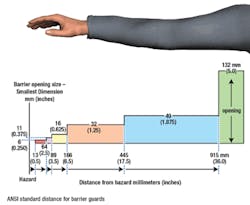
A guard must ensure that individuals cannot reach the hazard by reaching over, under, around or through it. To determine the safe mounting distance for a barrier guard, first consider the largest opening in the guarding material. The current OSHA standard for safe distance as a function of opening size is set forth in Table O-10 of OSHA 29 CFR 1910.217 – Mechanical Power Presses. This table technically only applies to mechanical power presses operated within OSHA’s jurisdiction, although some industry consensus standards also reference this table, such as ANSI B65.1-2005, a safety standard for printing press systems.
A 1995 study, A Review of Machine Guarding Recommendations, conducted by the Liberty Mutual Research Center for Health and Safety, is the basis for the ANSI and CSA standards. This anthropomorphic study, shown in Figure 2, was based on the then-current U.S. work force. While not officially adopted by OSHA, these standards have been adopted by a number of other consensus standards, including (among others):
- ANSI B11.19-2010 – Performance Criteria for Safeguarding
- ANSI/RIA R15.06-1999 (R2009) – For Industrial Robots and Robot Systems – Safety Requirements
- CSA Z432-04 – Safeguarding of Machinery – Occupational Health and Safety.
Reach under – To prevent an individual from accessing the hazard by reaching or crawling below the barrier guard, perimeter barrier guards must be designed so that the bottom of the barrier is no more than 300 mm (1 foot) above the adjacent walking surface according to ANSI/RIA R15.06-1999 (R2009). The same standard states that the top of the barrier must be no less than 1,500 mm (5 feet) above the adjacent walking surface. These measurements are more restrictive in Canada with distances of 150 mm (6 inches) and 1,800 mm (71 inches), respectively, according to CSA Z434-03. The equivalent international standard, ISO 10218-2:2011, sets the requirements at 200 mm (7.8 inches) and 1,400 mm (55 inches), respectively.
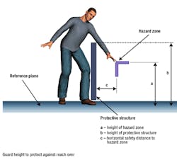
Reach over – Figure 3 shows how to determine guard height to protect against reaching over a barrier to contact a hazard. In the figure, “a” is the height of the danger zone, “b” is the height of the protective structure and “c” is the horizontal distance between the guard and the danger zone. Guards or other protective structures less than 1,000 mm high (39 inches) are not considered sufficient on their own for any application because they do not adequately restrict movement of the body, and structures less than 1,400 mm high (55 inches) should not be used in high-risk applications without additional safety measures. The following guidelines are available to help determine adequate height of constructed guards in relation to the hazard height and the distance of the guard from hazard:
- ANSI B11.19-2010 – Performance Criteria for Safeguarding
- CSA Z432-04 – Safeguarding of Machinery – Occupational Health and Safety
- ISO 13857:2008 – Safety of Machinery – Safety distances to prevent hazard zones being reached by upper and lower limbs.
- Note that ANSI B15.1-2000 (R2006) – Safety Standard for Mechanical Power Transmission Apparatus included similar requirements, but has since been withdrawn and replaced in part by ANSI B11.19-2010.
Presence Sensing Devices
Safety devices that protect individuals by detecting their entrance to or presence within a hazardous area include photoelectric presence sensing devices (including light curtains, single-beam devices and laser area scanners). Light curtains often are used in conjunction with hard guards to protect people when the machinery is operating.
Light curtains control access to the hazardous equipment by emitting infrared light beams, typically across the entrance to the hazardous area. When any of the beams is blocked, the light curtain control circuit sends a stop signal to the guarded machine. Light curtains are very versatile and can guard an area many meters wide.
Pressure sensitive safety mats provide another alternative for guarding the equipment entrance. They also may be installed to protect the inside of a cell. A matrix of interconnected mats can be laid at the entry area and an operator’s footstep causes the mat control unit to send a stop signal to the machine. Trim is used around the perimeter of the mat to hold it in place, protect wiring and provide a ramped surface to prevent tripping hazards.
Safeguarding devices, such as presence sensing devices, that do not prevent an individual from reaching into a hazardous area must be located far enough away from the hazardous area that the machine will stop before the operator’s hand or other body part can reach the hazard. The minimum safe distance is based on the stopping time of the machine as well as the reaction time of the safeguarding device and the estimated approach speed of the individual towards the hazard.
A formula is included in ANSI standards B11.19-2010 and Robotic Industries Association (RIA) R15.06-1999 (R2009), as well as CSA Z142-10, Z432-04 and Z434-03. This newer formula that takes several factors into consideration when calculating the minimum safe distance. I suggest using this newer formula in the form used by ANSI and CSA:
DS = K (T) + DPF
where:
DS = the safety distance
K = the maximum speed that an individual can approach the hazard
T = the total time to stop the hazardous motion
DPF = the depth penetration factor of the safeguarding device
Depth Penetration Factor
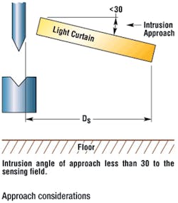
The depth penetration factor (DPF) must be added to the safety distance when using devices that do not detect the presence of an individual at the plane or within the field until an amount of penetration into the field occurs. The expected direction of approach towards the hazard should be considered when calculating the depth penetration factor. If the detection zone is at an angle of greater than 30 degrees to the direction of approach as in Figure 4, it is treated as a perpendicular approach. If the detection zone has been installed so that it is angled less than 30 degrees to the direction of approach, it is treated as a parallel approach.
The depth penetration factor compensates for varying object sensitivities of electro-optical presence sensing devices.
Accurate calculation of the minimum safe mounting distance for many safeguarding devices can ensure the safety of personnel while conserving floor space and maximizing throughput. In manufacturing operations, the two most important considerations are safety and productivity. Proper calculation of the required safety distance is necessary to select appropriate safeguarding measures and optimize both productivity and safety.
Space limitations make it impossible to address every possible situation or to fully explain every configuration option, so it’s important to consult your vendor and the appropriate safety standards on how to optimize safety device implementation for your specific application.
Chris Soranno is the safety compliance manager for the Machine Services Division of Omron Automation and Safety. Soranno has been with Omron Automation and Safety for 10 years and has extensive experience performing onsite machine safeguarding assessments, training customers on safety and standards and actively participating on more than a dozen various domestic and international consensus safety standards. He can be reached via e-mail at [email protected].
