Energy Control Planning: A Guide to the Key Lockout/Tagout Considerations
Energy is useful. If controlled correctly it can create value and be put to good use. However, it is, by its very thermodynamic nature, potentially harmful and must be carefully contained within the domain in which it has been designed to remain. If it escapes, for any reason, people can be hurt.
Normally, during the routine operation of plant equipment, energy is confined and contained within the equipment by various means. Usually, a good strong and robust mechanical integrity program ensures that the energy – whatever it may be – stays where it is meant to be. Occasionally however, equipment must be shut down for maintenance or cleaning or some other transient reason. Then human beings can and do interact with equipment that may still carry energy.
Naturally, the real goal is to eliminate or reduce these transient conditions through better reliability. Studies show that more reliable equipment translates to better safety. As maintenance shutdowns are, however, a reality of plant operation, I will examine the scenarios of energy control in normal routine maintenance preparation that do occur, but will not address the specific planning that goes into big events such as turnarounds.
When work must be carried out on equipment that carries energy under normal conditions, standard accepted practices on lockout/tagout (LOTO) apply. There are various guidelines for LOTO practices including OSHA and ANSI. I’m not not going to examine the specific equipment of LOTO (locks, chains, tags, etc.), but will suggest that the overall process of isolating equipment from energy can be planned and executed in such a way as to identify and mitigate hidden risks. This process is called energy control planning, and the product of the risk assessment and execution process is an energy control plan (ECP).
Energy Control Planning
When maintenance jobs are planned and controlled through a permit-to-work (PTW) system, the main focus of risk control frequently is on the task itself, whether that is cold work, hot work, confined space work, etc. The PTW system used by many companies includes LOTO permits or may have references to the LOTO process in other PTW system.
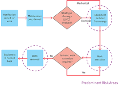
Energy control planning recognizes that in order to carry out maintenance on energized equipment three main hazard areas must be controlled. These are:
- Isolating the energy;
- The de-energized maintenance work itself, and
- The process of de-isolation.
This is illustrated in Figure 1 below:
Figure 1: The LOTO process showing predominant risk areas.
There may be additional operational risks associated with a shutdown or when re-energizing and restarting equipment, but ECPs tend to focus on the risks associated with (1) and (3) above. Process (2) risks should be taken care of in the job hazard analysis (JHA) or risk assessment through maintenance planning.
The types of questions that therefore must be asked and answered in considering the energy control process include the following:
- What type of energy is involved?
- What is the worst that can happen?
- Is the risk of isolation higher that the risk it mitigates?
- Is a “line break” involved?
- Will the work be completed in one shift?
Isolating equipment is a hazardous process in itself. Preparation of the isolation is a process that is best carried out in a planned – not ad hoc or reactive – manner. There are some basic principles for safe isolation of a job so that maintenance can be performed. One of the most important mantras is: As far as possible, each person who interacts with the isolated equipment must have his own personal control (usually a lock) on the energy that could harm him.
Often, this is the starting place for best practice in isolations. In some geographical regions, often those with less regulation, the common practice is supervisor-led lockouts. Work performers (often contractors) rely on the supervisor lock AND the administrative barrier of good communication with the supervisor to ensure that the lock is not removed while work continues to be performed. This is a best practice but unfortunately, it is a common practice.
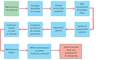
This risk as well as others must be taken into account when preparing for isolation. The energy control process follows a number of general steps as outlined in Figure 2:
Figure 2: Energy control process planning steps
It also is a good practice for production/operations areas to produce good codified standard operating procedures (SOPs) that include “preparing XXX equipment for maintenance” that directly refer to ECP aspects. Indeed, electrical safety procedures specifically may be written for high-voltage isolations and switching as well as other aspects that can be cross-referenced in a good ECP.
The goal is not to generate a mountain of paperwork, but to control and plan out the potential surprises in mechanical interventions involving high-hazardous processes with multiple energies. Codified procedures are therefore a good thing. Tacit knowledge and assumptions alone are dangerous.
Mapping It Out
Indeed, some of these codified procedures can be split down further. In fact, best practice for energy control planning and execution is to codify the process in a swim-lane diagram similar to the excerpt shown in Figure 3:
Figure 3: A typical swim-lane process map addressing key roles in ECP execution
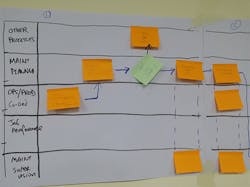
This kind of approach can be mapped out by a team that includes safety professionals, operations area authority and maintenance workers, and ensures that it is clear who does what exactly and when, who leads, who is involved and what comes next. Note, however, that this mapping process should be led by a recognized and qualified isolation expert. Qualification and competence can and should be specified as will be explained later.
The swim-lane process (Figure 3) begins with key roles involved in the process then considers who does what and in what sequence. The diagram uses squares for steps and diamonds for questions. The process should consider the risk of the actual task, the risk of the isolation and de-isolation and the energies involved, as well as line breaks or other isolation considerations. Typically, this mapping process is conducted with the key roles involved using post-its and A0 sheets of paper, as illustrated in Figure 4 below.
Figure 4: Typical example of a team process where ECP is mapped out and clarified with the key roles.
Recognizing a Line Break
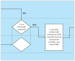
Figure 5: Is a line break required?
As mentioned earlier, one of the most important questions to be asked in the planning process for the safe isolation of an energy is whether a line break is involved (Figure 5 above). To answer that question there needs to be an understanding of what constitutes a line break.
According to OSHA standard 29 CFR 1910.147 (2), a line break means “the intentional opening of a pipe, line or duct that is or has been carrying flammable, corrosive or toxic material, an inert gas, or any fluid at a volume, pressure or temperature capable of causing injury.” Specifically, this can include the following examples:
- Breaking flanges
- Removing one or more bolts from flanges
- Opening valves to the atmosphere
- Removing valve bonnets and non-return valve caps
- Turning spectacle plates
- Breaking pipe joints
- Removing slip plates, blind flanges, plugs and caps
- Disconnecting tubing
- Disconnecting loading and unloading process hoses & removing blind flanges on loading/filling lines
- Penetrating a line by mechanical or other means (wet/hot tap)
- Opening inspection ports
- Making subtle adjustments (e.g., replacing packing on a valve)
- Collecting process samples from on-line processes
- Cleaning out in-line filters
As can be seen from this list, the actual process of carrying out a line break entails its own risks, even if it is only breaking a flange to slip in a spectacle plate as part of an isolation. This process first must be recognized. Once it has been, the appropriate measures to control the risk can be identified and applied. This would be part of a good ECP.
Stepping Out the Isolations
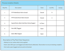
A simple example of a stepped-out isolation process involving a mechanical isolation of a hydrocarbon line to facilitate a PM on a pump (thus involving a “line break”), might look like Figure 6 below, incorporated into the ECP:
Figure 6: Example of stepped isolation process in ECP
The mitigation considerations of the hazards at these points will consider the PPE required (eg. chemical suit) and if/when PPE can be relaxed. Often, an isometric drawing or diagram can be included in the ECP to make crystal clear that the named and numbered valves from the P&ID are identified. The point of going to this detail on the ECP is to ensure planning always happens first before any action is taken.
The worst-case scenario is to arrive with a crew on the day, have the permits signed for the work to be carried out, then perform the isolation ad hoc, miss something or forget to consider it due to time constraints or production pressure, and then find that a surprise event occurs.
This is where the ECP Planning process comes in to ensure the isolation steps are codified. Once used successfully, the ECP can be archived, reviewed and re-used again and again.
Hierarchy of Mechanical Isolations
When carrying out mechanical isolations, there usually is a hierarchy of mechanical options depending on the level of risk mitigation that is required. One of the highest risk situations is, for example, when a human being must enter a vessel or confined space to carry out an inspection or some kind of work on the inside. This is a potential life-death situation and must be viewed and handled accordingly.
The mechanical isolation of the vessel therefore must start with disconnections, venting and other measures. Dropping out spool pieces and opening the vessel as far as possible is key. Consideration must be given to the worst-case scenario.
Thereafter, various other means of isolating systems or equipment that contain hazards can be used. The hierarchy is, generally, as follows:
- Double block and controlled bleed;
- Block valve and blank/blind flange;
- Double block valves;
- Single block valve;
- Engineered process plug (i.e. solidify the process)
The degree of isolation depends on the hazards of the material being isolated, the configuration of the piping system, the frequency of the line break, the added risk of leaks from additional isolation valves and the experience gained from past line breaks.
Where work on hazardous systems is to be performed behind a single blocking valve, the line break permit or procedure should indicate how the hazard is to be mitigated, including worst case scenarios and contingency plans.
Assume Nothing, Verify Everything
There are many potential traps in the isolation process. One is the assumption that, once locks are in place, all is safe. This is never wise. It is absolutely vital in isolations to VERIFY that the energy has been removed. In the preparation of a good ECP, these steps are properly considered and gone through. They can be:
- Try – To try to run the equipment by trying to start it locally or from DCS;
- Test – To verify that there is no residual energy such as electrical energy by “test before touch,” and,
- Clear – To verify that the pipework is clear of residual harmful chemicals and that people are clear of energy during any test or try stage.
Planning and thinking through in advance how and what to do if there is a surprise is vital to ensuring isolations safely can be carried out. It is not unknown for the wrong equipment to be electrically isolated, for there to be dual feed of energy or for pockets of harmful chemicals remain in the equipment.
To define equipment cleared, the following are good guidelines:
Cleared: A determination that all lines and equipment associated with the system are verified to have been isolated and, where appropriate, drained, flushed and/or purged of hazardous material, and the following criteria are met:
- The system’s temperature is lower than 60°C and higher than -10°C.
- Atmospheric pressure has been attained.
- Hazards associated with toxicity, corrosiveness, flammability of gases, vapors or mists and/or airborne combustible dust are reduced to acceptable levels and verified with acceptable test methods such as pH litmus paper, detector tube or oxygen analyzer.
These or similar stipulations should be part of ECP in both the planning and execution phase.
Training and Competence
Having mapped out the process in a swim-lane flowchart, it will become clear what the key roles are and who leads key steps. This makes the identification and targeting of training more precise. To write an ECP, someone takes the lead, and this person takes on the role of ECP coordinator.
This role usually is performed by someone from the area, with owner authority in production/operations. This is not usually or necessarily a full-time role or job, but is performed by someone like a shift engineer or lead operator or whomever has the appropriate knowledge and skills to understand the hazards and the process in the area and owns the equipment.
The key roles in the ECP process are:
- ECP coordinator
- Job performers (including contractors and supervision)
- Area authority (including operators, supervision)
- Maintenance planner (depends on the site practices, but the planner can archive and access ECPs again for future jobs to prepare the job package with the area authority)
Therefore, competence training can be targeted at 3 levels:
- General overview – What is ECP and why is it important?
- User – My role as area authority or job performer;
- Expert – ECP coordinator.
Once training is identified and competence levels determined, it is vital to complete the loop through a verification of competence process. Classroom and e-learning are good tools, testing afterwards for understanding is excellent, but better still is to work with demonstrated examples of good ECPs and the roles people played in their implementation. An ECP coordinator might need to demonstrate six ECPs that cover mechanical, electrical, chemical and other energies. This may involve him or her building a personal portfolio of his/her competence. Re-validation processes (at appropriate intervals) also must be considered, as well as MOC-personnel implications.
Consequences Can Be Fatal
The consequence of a loss of primary containment of energy can be fatal. Obviously, it is vital that all energies are identified and appropriately isolated, but the process to consider all the steps and implications must be thought out in advance using an ECP.
Businesses should ensure that they have clear instructions, procedures, policies and competence training in place for these important aspects of ECP. In many jurisdictions, this is mandated by regulations.
Senior managers at the site or business must understand and accept their responsibilities for ensuring competence verification. They should lead the sampling of the execution of ECPs by taking a personal interest and making regular field visits to engage with the roles who carry out the ECP.
The ECP is a good process for planning out and codifying the isolation processes, which in themselves carry some inherent risks. Good ECPs can and should be archived and re-verified and re-used for repeat jobs. They work in conjunction with good SOPs, PTW, risk assessments and maintenance job planning.
There are many standards and resources and best practices available to help business implement strong barriers and ECP, with basic essentials summarized. Among these are protocols for ECP developed by DuPont based on the above premises. These have been used extensively and successfully for many years in our own hazardous facilities and have helped client companies to improve in this general risk area.
